Inserting bridles
|
Tool |
Tool set |
|
Bridle
|
Rigging/Braceworks |

The Bridle tool places a bridle object in the drawing. Bridle legs can be inserted on house rigging points and rigging objects, and on structural members if this option is enabled when setting the bridle preferences. The down leg uses a bridle part by default, but you can choose to use a hoist instead.
For consistency, the default bridle parameters should be set before placement, either by clicking Preferences from the Tool bar or by selecting the Bridle Preferences command. See Bridle preferences.
Before a bridle is inserted, make sure the necessary rigging points are present in the drawing.
|
Mode |
Description |
|
Auto Insertion
|
Inserts the bridle with one click to define the connection point; the legs are automatically inserted on the closest rigging points |
|
Click Insertion
|
Inserts the bridle with multiple clicks, to define the connection point and each leg insertion point |
|
Deadhang
|
Inserts a dead hang object, to suspend a load directly below a rigging point |
|
Two Leg Bridle
|
Inserts a two leg bridle |
|
Reversed Two Leg Bridle
|
Inserts a reversed two leg bridle, to connect multiple objects to a rigging point. Inserting an inverted bridle requires three clicks. The first two clicks designate the attachment points on the truss system; the third click sets the down leg or hoist location. To calculate the forces correctly with Braceworks, the objects must be on the same truss system. |
|
Three Leg Bridle
|
Inserts a three leg bridle |
|
Four Leg Bridle
|
Inserts a four leg bridle |
|
Stacked Bridle
|
Inserts a stacked bridle, which is structurally determinate |
|
Trim Height |
When Click Insertion is selected in Top/Plan view, enter the distance from the bottom of the bridle to the floor |
|
Automatic Numbering
|
When toggled on, enables automatic numbering as objects are placed |
|
Automatic Numbering Preferences
|
Sets the automatic numbering preferences |
|
|
Selects the default options for the bridle |


Inserting bridles manually
|
Mode |
Tool |
Tool set |
|
Click Insertion
|
Bridle
|
Rigging/Braceworks |
The Click Insertion mode uses multiple clicks to insert a bridle object. For most bridle types, the first click defines the bridle’s connection point on the object it will support, and subsequent clicks define the leg insertion points. Reversed two leg bridles are inserted differently.
To insert a bridle manually:
Click the tool and insertion mode.
Click the desired bridle type mode.
If you are working in Top/Plan view, enter the Trim Height of the bridle on the Tool bar.
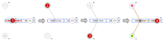
If inserting a two leg bridle, which is the most common, do the following.
Click to set the insertion point for the top Leg 1, and click again to set the insertion point for the top of Leg 2. The available insertion points are highlighted as the mouse moves over them.
Click a third time to set the down leg, on a line between the first two points. Valid insertion points are highlighted as the mouse moves over them. The bridle object is inserted in the drawing.
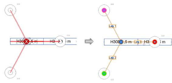
If inserting a reversed two leg bridle, do the following. If inserting any other bridle type, proceed to step 8.
Click on the rigging object to set the insertion point for Leg 1, and click again to set the insertion point for Leg 2. The available insertion points are highlighted as the mouse moves over them.
Click on the rigging point where the bridle will attach. Valid insertion points are highlighted as the mouse moves over them. The bridle object is inserted in the drawing.
Move the mouse to the object that the bridle will support, and click to set the connection point. Valid connection points are highlighted as the mouse moves over them.
Insert the bridle legs. For each leg, click on the rigging point where the leg will attach. The available insertion points are highlighted as the mouse moves over them.
The bridle object is inserted in the drawing.
The bridle parameters can be edited later from the Object Info palette; see Bridle properties.
A different type of hoist can be selected for the down leg by clicking Replace Down Leg with Hoist on the Object Info palette.
Inserting bridles automatically
|
Mode |
Tool |
Tool set |
|
Auto Insertion
|
Bridle
|
Rigging/Braceworks |
To insert a bridle automatically:
Click the tool and insertion mode.
Click the desired bridle type mode.
The Auto Insertion mode is not available when inserting reversed two leg bridles.
Move the mouse to the object that the bridle will support.
Using Auto Connect technology, the valid connection points are highlighted, and a preview of the bridle legs is dynamically displayed.
Click on the rigging object to insert the bridle as previewed.
The bridle is inserted in the drawing according to the settings in the Bridle preferences dialog box.
The bridle parameters can be edited later from the Object Info palette; see Bridle properties.
A different type of hoist can be selected for the down leg by clicking Replace Down Leg with Hoist on the Object Info palette.